
AROFLEX Torque Limiter Technical Guide
Complete reference for installation, running-in, limit switch integration, machining tolerances and product data for ATL friction disc, chain coupling, elastomeric, and shear torque limiter ranges.
Section 1
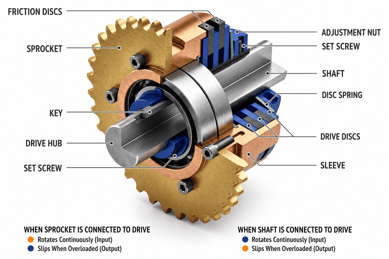
Installation Instructions for ATL Torque Limiters
Before assembly, ensure all components are thoroughly cleaned and inspected. Follow the sequence below precisely.
Fit the Pilot Bush
Slide the bronze pilot bush onto the torque limiter hub.
First Friction Facing
Slide the first non-asbestos friction facing over the hub so it sits flush over the bush.
Mount Centre Member
Mount your centre member (platewheel, sprocket, or pulley) onto the bronze bush.
Second Friction Facing
Slide the second friction facing on, ensuring it sits squarely on the bush against the centre member.
Pressure Plate
Install the steel pressure plate.
Disc Springs
Adjusting Nut
For standard models, fit the pilot plate or lock-washer, then thread on the adjusting nut.
Section 2
Mandatory Running-In Procedure
Friction torque limiters must be run-in to burnish the friction discs and achieve consistent, accurate slip torques.
Section 3
Use and Installation of Limit Switches
Friction limiters are mechanical fuses - they do not stop the driving motor. Left to slip during a jam, they generate extreme heat that will glaze friction facings or create a fire risk.
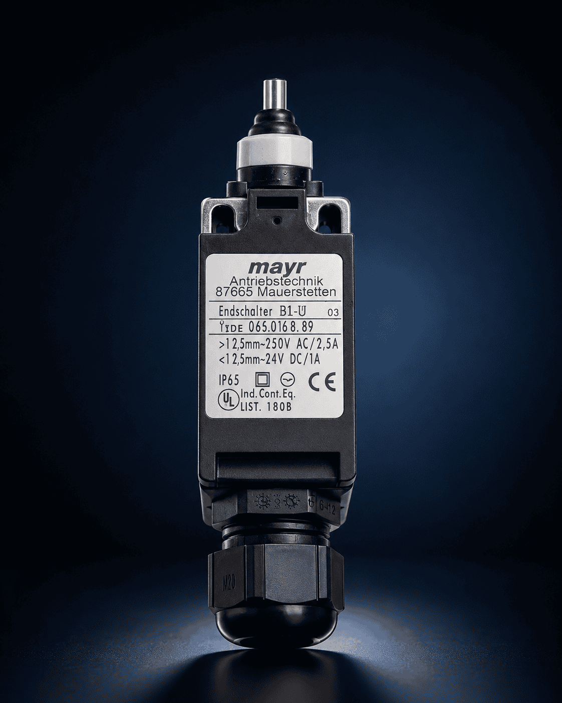
EM1 vs EM2
Use EM1 (Inductive Proximity) for clean or dusty areas. Use EM2 (Mechanical Plunger) for heavy washdown zones such as bakery conveyors.
Actuation Plate
Position the switch to interact with the limiter's axial actuation plate. For the EM2, the plunger should be depressed by 1-3mm immediately on a trip.
Fail-Safe (NC)
Always wire using Normally Closed (NC) contact logic. If a wire is severed, the circuit opens and instantly stops the motor.

Technical Reference
Critical Machining Tolerances
To ensure the AROFLEX unit operates effectively without vibration or premature failure, adhere to these strict standards.
Product Range
AROFLEX Product Specifications
Full dimensional and torque capacity data for every AROFLEX torque limiter and coupling family. Select a product range below.
Chain Coupling
AROFLEX ATLC
Torque limiter combined with duplex roller chain flexible coupling. Eleven standard sizes combining overload protection with in-line shaft connection.
2.94 - 10,000 NmElastomeric Coupling
ATL RN & ATL RB
Elastomeric torque limiter couplings in JAW (RN) and Pin & Bush (RB) configurations. Smooth power transmission with built-in overload protection.
2.94 - 1,088.54 NmShear Coupling
SRB & NFS Shear
Positive disconnect shear torque limiter couplings in Pin & Bush (SRB) and Jaw (NFS) types. Wedge pin ratings adjustable to precise torque values.
331 - 23,000 NmChain Coupling
AROFLEX ATLC - Torque Limiter Chain Coupling
Torque limiter combined with duplex roller chain flexible coupling. Eleven standard sizes. All dimensions in mm.
Your browser cannot display the PDF inline. Open in a new tab →
Elastomeric Coupling
ATL RN (JAW) & ATL RB (Pin & Bush)
Elastomeric torque limiter couplings in JAW and Pin & Bush configurations. All dimensions in mm.
Your browser cannot display the PDF inline. Open in a new tab →
Shear Coupling
SRB (Pin & Bush) & NFS (JAW) Shear Torque Limiter
Positive disconnect shear couplings up to 23,000 Nm. Torque adjustable by Wedge Pin ratings.
Your browser cannot display the PDF inline. Open in a new tab →
Installation & Maintenance
ATLC Torque Limiters - Installation & Maintenance Guide
Official Arrow Engineering guide covering assembly, running-in, torque setting, checking, couplings and maintenance. Models ATLC 14 to ATLC 64.
Your browser cannot display the PDF inline. Open in a new tab →
Upgrades
Alternative Technologies
Option 1
Indent Ball Limiters
e.g. Mayr EAS Compact / Compomac ZBC. Spring-loaded balls in detents pop out under overload for instant mechanical disconnect.
Advantages
- Zero-backlash precision and instant disconnect with no heat.
- Synchronous re-engagement at exact 360° home position.
- Sealed stainless (EAS-Compact-R) for hygienic washdown.
Disadvantages
Will clatter continuously if the motor isn't switched off - a limit switch is mandatory.
Option 2
Positive Disconnect Limiters
e.g. Wedgegard / Shear Pin. A hardened wedge or pin physically shears at a precise torque to completely disconnect the drive.
Advantages
- Absolute circuit breaker - motor spins free with zero heat.
- Highly accurate torque precision (±5%).
- Handles extreme torques up to 125,000 Nm.
Disadvantages
Reset is manual and consumable. Operator must replace the broken wedge pin - unsuitable for frequent nuisance jams.